Links
Tags
An Arcade Machine of Sorts
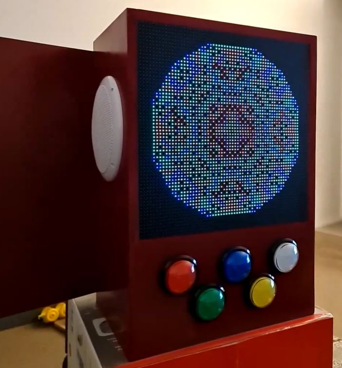
About a month ago, I posted about testing out a P5 Panel I'd acquired during an end of financial year sale from one of my go-to suppliers. This weekend, I've had a chance now to do something a little more permanent with those panels by building an arcade machine. As my son becomes a little more interactive with things, it'll be a fun way to program a few little games for him to muck about with.
The first step for this build was to pull out my trusty old version of Sketchup 2017 and draw out a basic frame. Inside of this, some 60mm illuminated buttons from Amazon, 2 x P5 Panels and 2 x 165mm marine speakers will need to fit into the chassis. I made sure to also include the width of the MDF when measuring out the box to ensure we're not the 40mm short for the speakers to comfortably sit.
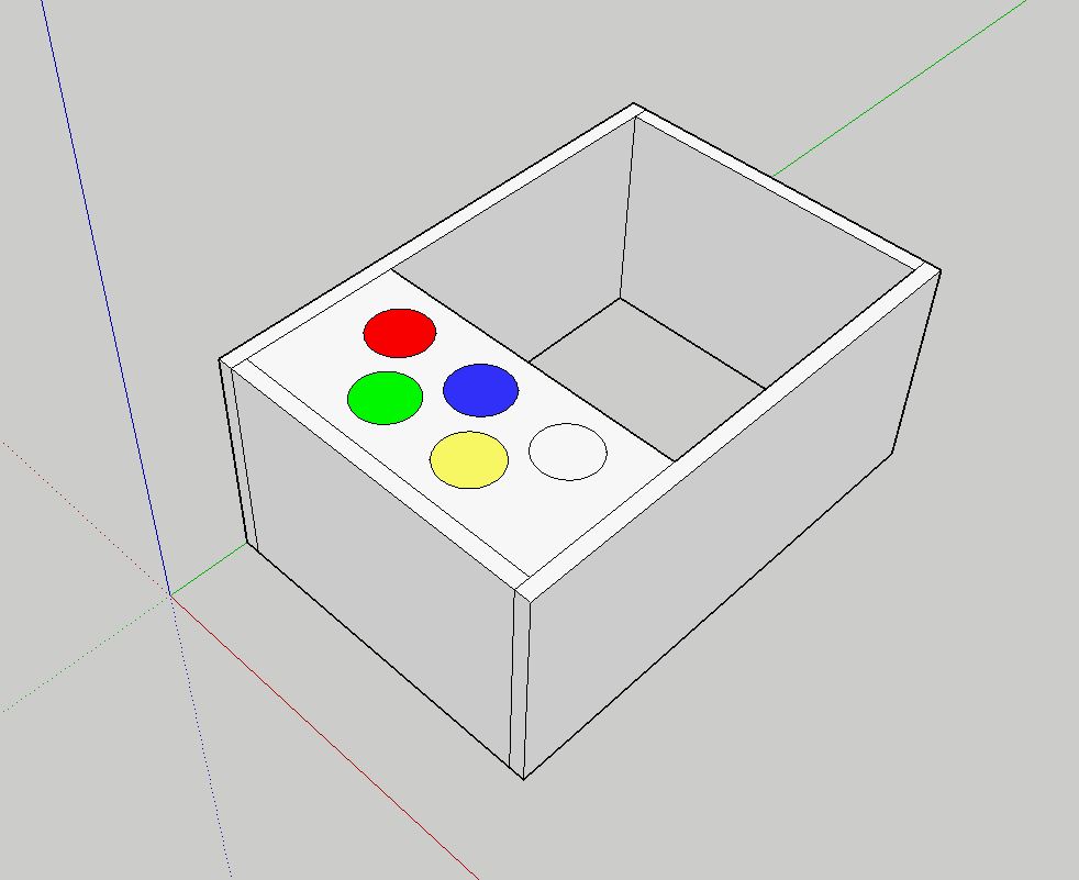
I've opted to go straight lines with this, we can use a routing bit or T-moulding to clean this up later - but otherwise straight lines are going to be infinitely easier to work with here, and will support some vertical mounting later. With each of these panels determined, it was time to go to Bunnings to find some suitable MDF. In this case, it won't be exposed to weather so the ease of working with MDF over Plywood was the deciding factor here, but you could quite easily go the Plywood route if you wanted something a little more solid. I got some 1200mm x 600mm x 16mm MDF (as T-moulding usually comes in 16mm), some red spray paint and got to work cutting the panels out.
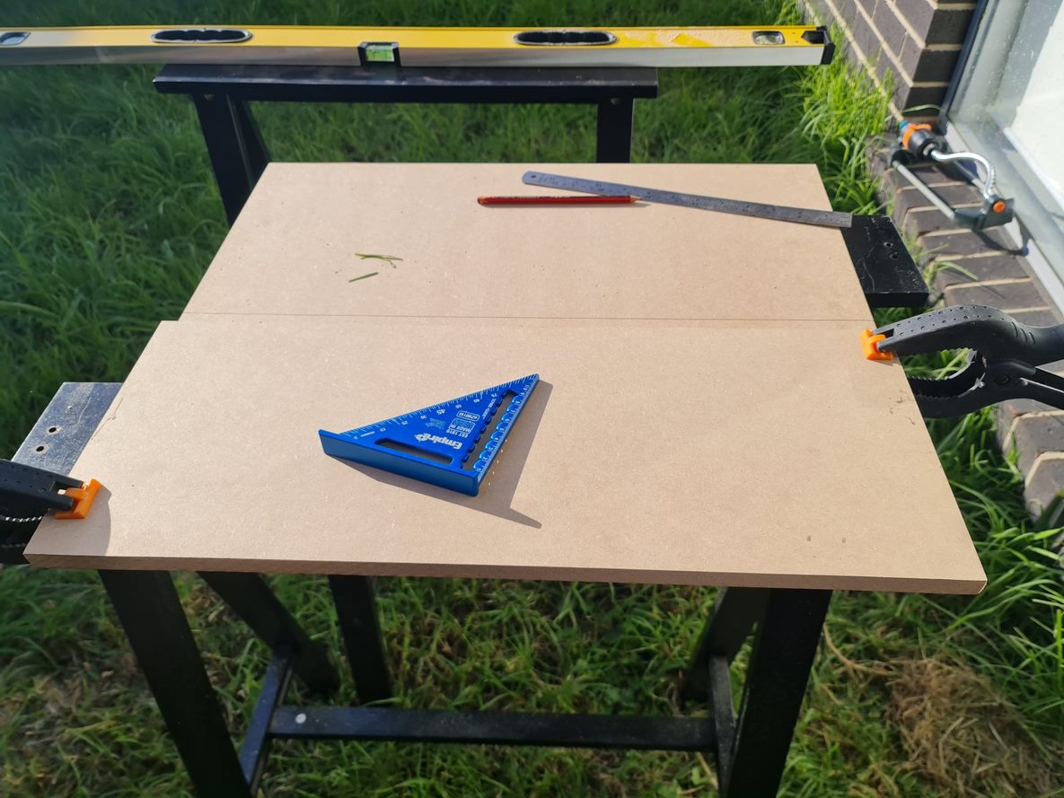
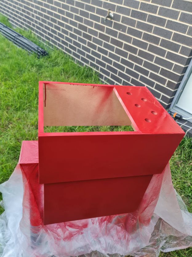
Yeah, that lawn really needs mowing - but given how wet it's been around here, it's been near impossible to find a good enough day that won't involve mud flinging from one side to the other. That aside, once it was all cut out and sanded back to the right size, some drilling + wood screws got the box assembled pretty easily. I used a hole saw bit with the drill to get the holes in for the arcade button - taking care to drill the pilot hole first, and cutting about 50% of the way in first before finishing from the other side. The advantage of doing this is you won't end up with any chipped wood as a result of the final bit being cut off (lesson learned from a previous arcade project!). All assembled to ensure things fit, it was time to get the wood filler to patch any holes before painting.
With the components all fitting nicely, it was time to print some joiners for the screens so that they line up as good as possible, while giving me something to screw into the chassis. Thankfully, someone had already designed some joiners so I didn't have to go out of my way to design them myself. With those on the printer, I had to make a door for the back and add some hinges. With that out of the way, it was time to paint. Now, I suck at painting - I can never get the right amount of spray paint on this. I was doing well until the final coat - but overall it's a nice colour - given my son's favourite colour right now is "James".
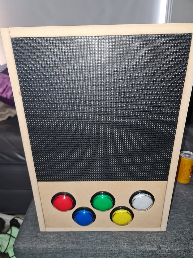
After a few coats of paint and an overnight dry, it was time to cut the holes for the speakers out by drawing a circle around 135mm diameter. Now, I don't have a protractor but I did have a ruler with a hole and a screw - so I was able to fashion something out of a ruler, marker and screw to draw a circle. With a large drill bit and a jig saw, the hole was in place and ready for installation.
Ok! This is starting to look pretty cool, still need to wire up the buttons and speakers. To do the speakers, I'd ordered a super cheap 50W amplifier board from Amazon while waiting for some slightly better ones to come along. This would allow for the marine speakers to have enough 5V juice to make some noise. Despite some crackling, the speakers are pretty good for some cheapies from DJ City. They'll do for some outdoor speakers mounted inside some resin rocks I'm planning for later in the year! I won't link the amplifier here, but any TPA3116D2 based amplifier will work here. With that wired in, I had a few USB sound cards in use here for a Raspberry Pi Zero. As the P5 Panels need the hardware pulse that is normally reserved for audio (otherwise you get lots of flickering), it's not a problem to use whatever USB sound card you might have lying around. I guess you could use HDMI audio if you can get the right converter.
For the button wiring, I had been using the rPi-P10 controller from Hanson electronics. You can of course wire this in manually if only using one chain, but this board does include some level shifters (3.3V to 5V) that will come in handy shortly. Unfortunately, the use of the level shifters means we can't detect any button presses. After jumping on the soldering iron, I'd pulled out a small PCB, several terminal connectors, used a tall-header GPIO Pin Header (to allow hat stacking), and wired on some Dupont connectors for lighting up the LEDs for the buttons individually. In hindsight, I might have replaced the buttons with some WS2811 LEDs to control the colour as well, maybe a future project than the LEDs with resistor values for 5V.
The rPi-P10 board is wired using this diagram - so reverse engineering it, I had determined I'll use the slots reserved for the second chain for the LED lights, and the third chain for buttons. I had confirmed the pinout works per the document before cutting away at pins. In the end, I had chopped 5 legs off the stacking connector so that they wouldn't pass through to the rPi-P10 hat for the buttons, and using Dupont connectors found the right R0/G0/B0/R1/B1 pins within the second connector so I could take advantage of the 5V level shifter on this board. You could simply use a level shifter and build your own board, but this crude board does the job for now. In the coming month, I'm going to give KiCad a go for this board and check out a process using JLCPCB or PCBWay to produce and send them through. It's so cheap these days to get custom PCBs, but it would have helped here to not have jump wires all over the board.
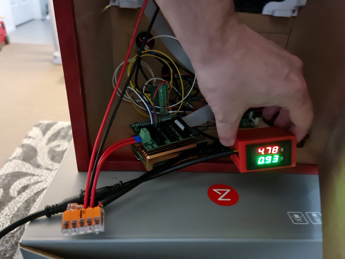
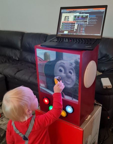
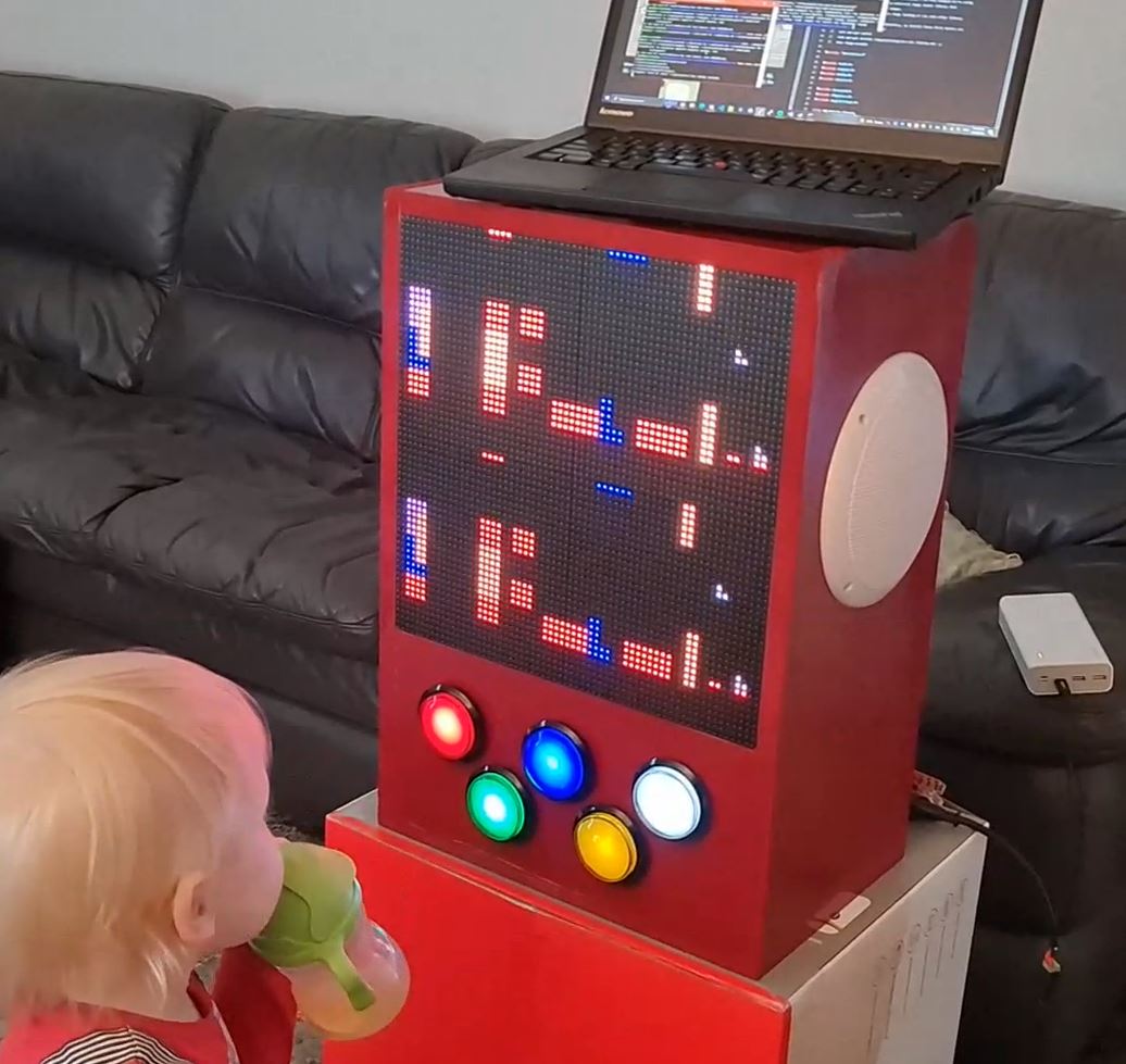
The final step was to wire it up, write some test code to ensure the buttons all work and to have some songs and pictures show up. Impressively, this set up under normal usage sits around 1A at 5V, so this whole thing is powered for several 10s of hours from a Romoss 30,000mAh battery. I had a Raspberry Pi 4 in at the time to do some debugging with (much faster to compile), but even that kept all lights lit and the matrix running at around that 1A mark (65% brightness). Obviously, the more white on the screen and loudness of the speakers all play a part, but impressive none-the-less.
Suffice to say as I sit here on a lazy Sunday afternoon, it looks pretty awesome and kiddo loves it too. Hopefully it'll give my phone five minutes of peace while we can code some things for it such as some low-res PICO-8 games that make use of the buttons.
Christmas in July - Plans for 2022's Christmas Light Show
Oh no! It's only six months until Christmas and there's so much to do! Ok... maybe not for most normal people - but for me, it's time to start ramping up planning to ensure plenty of time for sequencing and a few new props to add to the display.
Pre-buys, ordering and planning
The last few years have not been too kind on part shortages, transport, wars, pandemics - you name it. So much so, that this year if I was to order any lights, they needed to be done early on. In February this year, I pre-ordered a large quantity of LED lights from Light it Up LEDs. Best to order up at the start of the year so you can take advantage of sea-based shipping and any custom requirement you may have from wire gauges, separation between bulbs and connectors available within your string. Lucky for me, there were particular bulbs of interest in stock but if you need them and want to pay the lowest possible amount (which can be quite considerable), it can take several months for them to reach Australia with most in the community only receiving their bulbs in the last couple of weeks.
Secondly, I really needed to consolidate my Raspberry Pi's into one main controller box for the show. While consolidating everything might be a bad idea (one part = bad failure), it'll also help reduce the complexity and the amount of power injection required to light up those long strings. Interestingly, there are new controllers currently under development that will take advantage of the Raspberry Pi's additional GPIO pins called DPIPixels - it'll be interesting to see what form the product takes and how suitable Raspberry Pi Zero's might be at making cheap(ish) controllers. On the other end of the spectrum might well be dedicated controllers over at Experience Lights that made an appearance in the last couple of days. Exciting to see some new functions that will also reduce your build complexity for newcomers to the hobby.
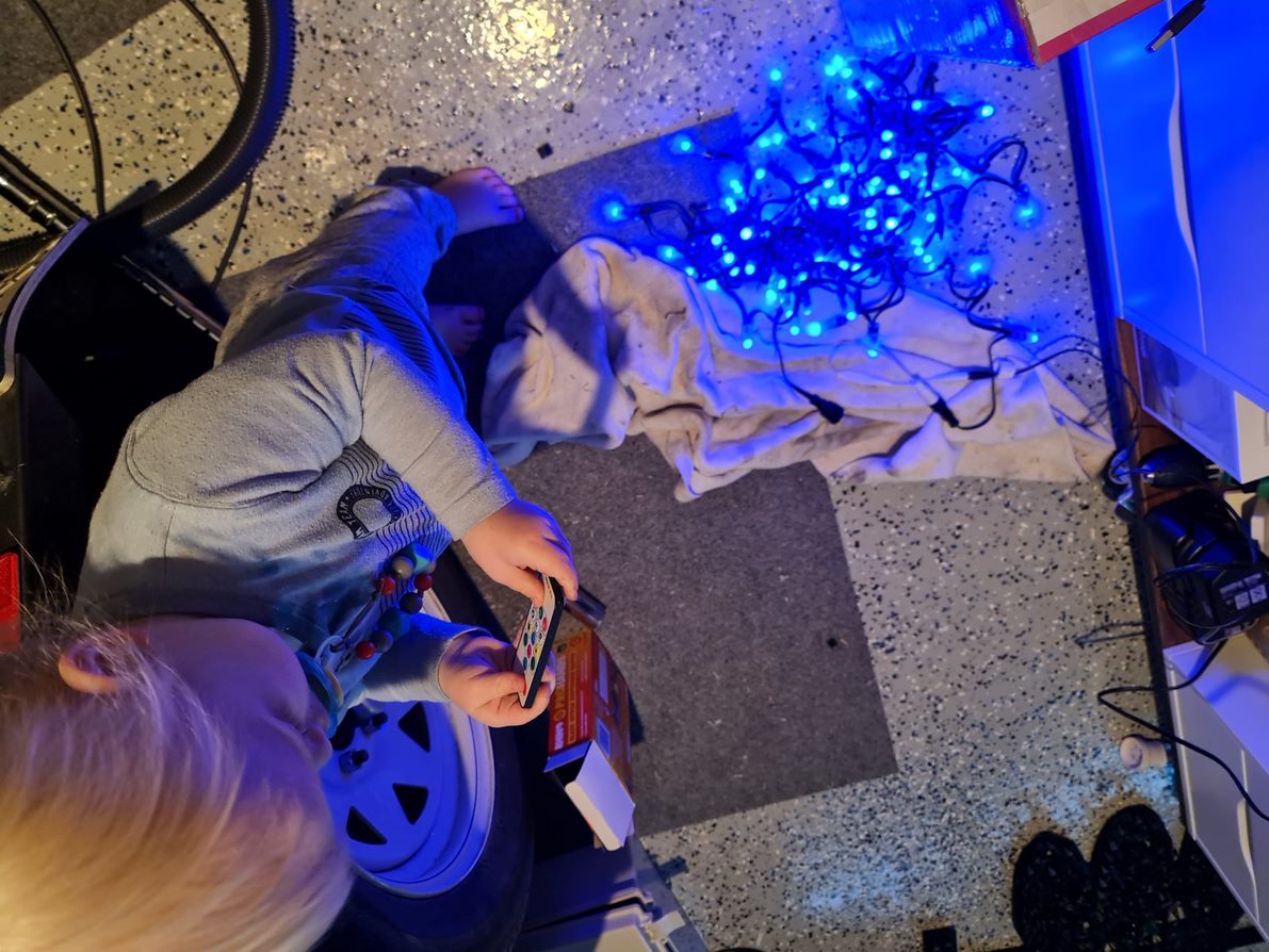
Thirdly, I'll need to crank up the 3D Printer again and procure a number of twin-wall sheets to start cutting out the new additions for this year's show. Thankfully, this year I have a new helper who has started helping by testing the LED bulbs from last year's poorly made matrix.
Assembling the new controller box
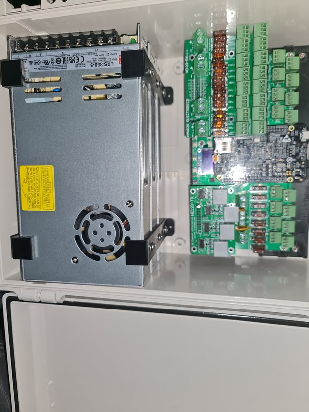
It's not been easy in finding the right components for this one. I figured this year I'd need a large enough box to store 3x 300w Meanwell power supplies in for both 5V and 12V running. This box, whilst having a lot of ports won't have a lot of lights hanging off of it. A few props and the LED strips amount to perhaps 2,500 lights total so as long as there's some separation, I should be able to get some reasonable airflow in there.
To begin, this year's controller of choice is Hanson Electronic's HE123mk2 controller. There are a number of reasons I like this one. (1) I get to put a Beaglebone to good use that I've had lying around for several years and (2) the board layout here ensures that the wiring itself does not cover up the fuses making it easy to spot dead fuses (they light up on failure) and replace them. It's a solid, well priced board with options to expand over your standard Cat5/6 cabling. This will cover any possible future expansion I might have, and the board looks to be very repairable. Given the chip shortage and inflated controller prices, these really do represent good value.
With components acquired and my previous box decimated for the power supplies, I got to work on 3D Printing a suitable apparatus for stacking Power Supplies. I only have a 200mm x 200mm 3D Printing Plate and this box is some 225mm wide. Naturally, you can print a plate around about 70mm x 225mm if you angle it 45 degrees, but then you need to watch for crazy 3D Print head movements to cater for your new angle. These won't be seen, so as long as I can print some platforms, I'll be able to screw things into place.
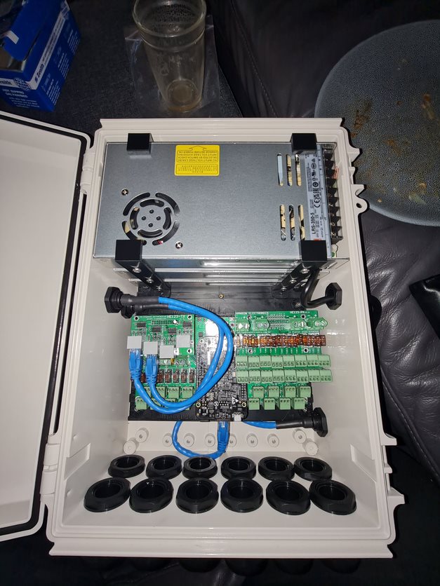
Now for a Pro Tip - I was able to source 4 hole cable glands on eBay from a Solar installer - these really do help reduce the swiss-cheese nature of the build but also provide a good way on managing the cables you need to pass through. You can also buy from Hanson Electronics (and this link is likely to continue working long after the eBay one expires) if white is your colour.
Pro Tip: When installing these, crimp your bootlace ferrules first, then thread the cable through the cap and rubber seal second, then push through the hole third before screwing into the terminal. If you don't, you won't get the cable through. At least my experience above is the rubber seal does not have a cutout to thread things through, and given the thickness of the LED connections, it's unlikely you'll get more than one through the cap.
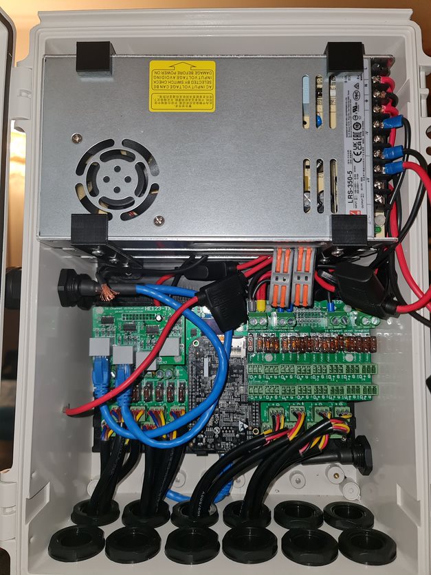
I'm no sparky which is why I don't do a detailed walkthrough of building a box, but it's a necessary evil in this hobby to be able to wire things up. After all, you can nearly guarantee you'll be replacing a bulb or two during the show - so you might as well get used to it now. In hindsight, I probably could have gone up a box size to help with airflow (still need to install fans on the cover to help push air through and work out how to get a temperature sensor working on the Beaglebone).
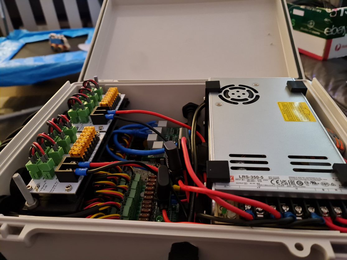
And that's it. unfortunately it's a little bit of a mess given the fuses all over the place but I do have 48 cables going out the bottom and room to mount a couple of fans to help with airflow. Overall I am quite happy with how this one came out - I managed to get the measurements right and holes lined up better than this time last year.
Anyway - that's enough Christmas talk for July. I've put up a resources page that I'll populate over the coming months with some STLs for this box and some sequences I used last year that are more unique than they were heavy inspirations of. You can check that out over here.